- 您现在的位置:买卖IC网 > Sheet目录462 > IXTH90N15T (IXYS)MOSFET N-CH 150V 90A TO247
Preliminary Technical Information
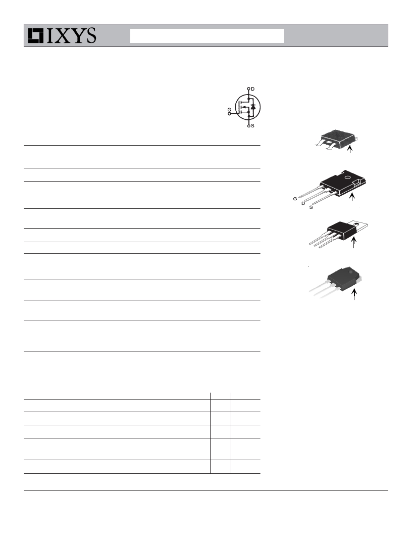
Trench Gate
Power MOSFET
N-Channel Enhancement Mode
IXTA90N15T
IXTH90N15T
IXTP90N15T
IXTQ90N15T
V DSS =
I D25 =
R DS(on) ≤
150V
90A
20m Ω
Avalanche Rated
TO-263 (I XTA )
Symbol
V DSS
V DGR
Test Conditions
T J = 25 ° C to 175 ° C
T J = 25 ° C to 175 ° C, R GS = 1M Ω
Maximum Ratings
150
150
V
V
G
S
TO-247 (IXTH)
(TAB)
V GSM
± 30
V
I D25
I LRMS
I DM
T C = 25 ° C *
Lead Current Limit, RMS
T C = 25 ° C, pulse width limited by T JM
90
75
250
A
A
A
(TAB)
I A
E AS
T C =
T C =
25 ° C
25 ° C
4
750
A
μ J
TO-220 (I XTP )
dV/dt
I S ≤ I DM , V DD ≤ V DSS , T J ≤ 175 ° C
10
V/ns
D
P D
T J
T JM
T stg
T C = 25 ° C
455
-55 ... +175
175
-55 ... +175
W
° C
° C
° C
G
S
TO-3P (IXTQ)
(TAB)
T L
T SOLD
M d
F C
1.6mm (0.062 in.) from case for 10s 300
Plastic body for 10 seconds 260
Mounting Torque(TO-220,TO-3P,TO-247) 1.13/10
Mounting Force (TO-263) 10..65/2.2..14.6
° C
° C
Nm/lb.in.
N/lb.
G
D
S
(TAB)
Weight
TO-263
TO-220
TO-3P
TO-247
2.5
3
5.5
6
g
g
g
g
G = Gate
S = Source
Features
D = Drain
TAB = Drain
International standard packages
Unclamped Inductive Switching (UIS)
rated
Low package inductance
Symbol Test Conditions
(T J = 25 ° C, unless otherwise specified)
Characteristic Values
Min. Typ. Max.
- easy to drive and to protect
BV DSS
V GS = 0V, I D = 250 μ A
150
V
Applications
V GS(th)
V DS = V GS , I D = 1mA
2.5
4.5
V
DC-DC converters
I GSS
V GS = ± 20V, V DS = 0V
± 200 nA
Battery chargers
Switched-mode and resonant-mode
I DSS
R DS(on)
V DS = V DSS
V GS = 0V T J = 150 ° C
V GS = 10V, I D = 0.5 ? I D25 , Note 1
17
5 μ A
250 μ A
20 m Ω
power supplies
DC choppers
AC motor control
Uninterruptible power supplies
? 2007 IXYS CORPORATION, All rights reserved
DS99857(08/07)
发布紧急采购,3分钟左右您将得到回复。
相关PDF资料
IXTI12N50P
MOSFET N-CH 500V 12A I2-PAK
IXTJ36N20
MOSFET N-CH 200V 36A TO-247AD
IXTK102N30P
MOSFET N-CH 300V 102A TO-264
IXTK110N30
MOSFET N-CH 300V 110A TO-264
IXTK120N20P
MOSFET N-CH 200V 120A TO-264
IXTK120N25P
MOSFET N-CH 250V 120A TO-264
IXTK120N25
MOSFET N-CH 250V 120A TO-264
IXTK128N15
MOSFET N-CH 150V 128A TO-264
相关代理商/技术参数
IXTH90P10P
功能描述:MOSFET -90.0 Amps -100V 0.250 Rds RoHS:否 制造商:STMicroelectronics 晶体管极性:N-Channel 汲极/源极击穿电压:650 V 闸/源击穿电压:25 V 漏极连续电流:130 A 电阻汲极/源极 RDS(导通):0.014 Ohms 配置:Single 最大工作温度: 安装风格:Through Hole 封装 / 箱体:Max247 封装:Tube
IXTH96N20P
功能描述:MOSFET 96 Amps 200V 0.024 Rds RoHS:否 制造商:STMicroelectronics 晶体管极性:N-Channel 汲极/源极击穿电压:650 V 闸/源击穿电压:25 V 漏极连续电流:130 A 电阻汲极/源极 RDS(导通):0.014 Ohms 配置:Single 最大工作温度: 安装风格:Through Hole 封装 / 箱体:Max247 封装:Tube
IXTH96N25T
功能描述:MOSFET 96 Amps 250V 36 Rds RoHS:否 制造商:STMicroelectronics 晶体管极性:N-Channel 汲极/源极击穿电压:650 V 闸/源击穿电压:25 V 漏极连续电流:130 A 电阻汲极/源极 RDS(导通):0.014 Ohms 配置:Single 最大工作温度: 安装风格:Through Hole 封装 / 箱体:Max247 封装:Tube
IXTH96P085T
功能描述:MOSFET -96 Amps -85V 0.013 Rds RoHS:否 制造商:STMicroelectronics 晶体管极性:N-Channel 汲极/源极击穿电压:650 V 闸/源击穿电压:25 V 漏极连续电流:130 A 电阻汲极/源极 RDS(导通):0.014 Ohms 配置:Single 最大工作温度: 安装风格:Through Hole 封装 / 箱体:Max247 封装:Tube
IXTH98N20T
功能描述:MOSFET 98 Amps 200V 26 Rds RoHS:否 制造商:STMicroelectronics 晶体管极性:N-Channel 汲极/源极击穿电压:650 V 闸/源击穿电压:25 V 漏极连续电流:130 A 电阻汲极/源极 RDS(导通):0.014 Ohms 配置:Single 最大工作温度: 安装风格:Through Hole 封装 / 箱体:Max247 封装:Tube
IXTH9N100
制造商:未知厂家 制造商全称:未知厂家 功能描述:TRANSISTOR | MOSFET | N-CHANNEL | 1KV V(BR)DSS | 9A I(D) | TO-218VAR
IXTH9N95
制造商:未知厂家 制造商全称:未知厂家 功能描述:TRANSISTOR | MOSFET | N-CHANNEL | 950V V(BR)DSS | 9A I(D) | TO-218VAR
IXTI10N60P
功能描述:MOSFET 10.0 Amps 600 V 0.74 Ohm Rds RoHS:否 制造商:STMicroelectronics 晶体管极性:N-Channel 汲极/源极击穿电压:650 V 闸/源击穿电压:25 V 漏极连续电流:130 A 电阻汲极/源极 RDS(导通):0.014 Ohms 配置:Single 最大工作温度: 安装风格:Through Hole 封装 / 箱体:Max247 封装:Tube
